

Chapter 5
I 1788 - State Of The Art In Textile Technology
II Australian Textiles - The Early Days
III Australian Textiles - The 20th Century
IV Australian Textiles - To Date
V Acknowledgements
References
Index
Search
Help
Contact us

By 1790, water power had been added to the mule, and the machine continued to be improved into the 19th Century. In some parts of the world, it is still the preferred approach to woollen-yarn manufacture, with none of the original principles changed, albeit now they are more automated.
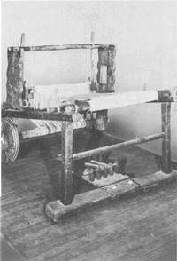
The time of colonization coincided with the first efforts to produce a power-loom, but it was to be another two decades before the problems in producing a reliable machine could be overcome. The most productive looms at that time were, therefore, manually operated. These looms (Fig. 8) had a rectangular framework, with the warp (lengthwise yarns) stretched from a beam (warm beam) at the rear to another beam (cloth beam or breast beam) at the front. The warp yarns were threaded through eyelets in the centres of a series of parallel 'needles' (made of wire) fixed together by cross-beams at the top and bottom (the heddle). There were at least two sets of heddles, with one yarn (or group of yarns) passing through one heddle and the next, adjacent yarn (or group of yarns) passing through the other heddle. Thus, raising or lowering of one of the foot operated heddles created a 'shed' through which the weft yarn on the shuttle could be projected. A swinging batten, hinged overhead, carried a reed; it was pushed towards the heddles before each 'pick' of weft yarn was inserted, and swung towards the weaver afterwards to 'beat up' (consolidate) the weft yarn against the previous weft yarn.

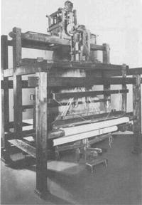
The main advance had occurred in 1733, when John Kay introduced his flying shuttle. Prior to this, a one-man loom produced a web two feet wide, the normal working stretch of the weaver's arms for throwing the shuttle. Kay's device (Fig. 9) comprised a 'lathe' (track) extending a foot on each side of the reed. Above the latter a sliding block or 'picker' was mounted on a rail, and a long card was attached to each picker. The home ends of the cords were joined in a peg or 'picking stick' held in the weaver's hand. When the shed had been formed, and the shuttle laid in the lathe, the weaver jerked and released the card. This caused both pickers to fly to the inner ends of their rails, and the shuttle was shot through the shed. As the pickers were returned to their places by springs, the opposite track was left clear to receive the shuttle. Thus, a jerk of the peg sent the shuttle through the shed in either direction, achieving a longer travel than the hand-thrown shuttle, and permitting a wider web of cloth.

 |
Australian Academy of Technological Sciences and Engineering |  |
© 1988 Print Edition pages 260 - 261, Online Edition 2000
Published by Australian Science and Technology Heritage Centre, using the Web Academic Resource Publisher
http://www.austehc.unimelb.edu.au/tia/270.html